.jpg)

.jpg)
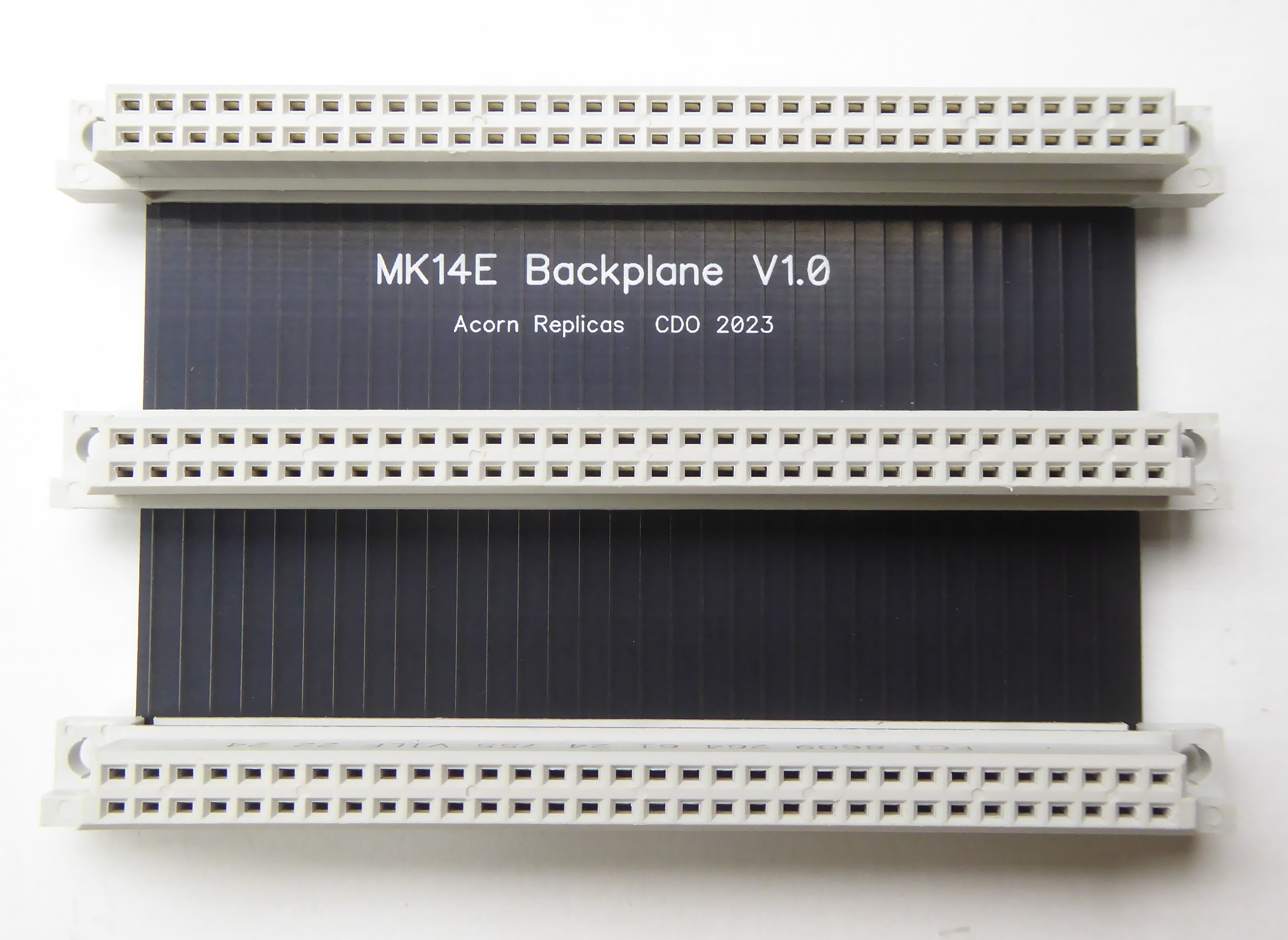
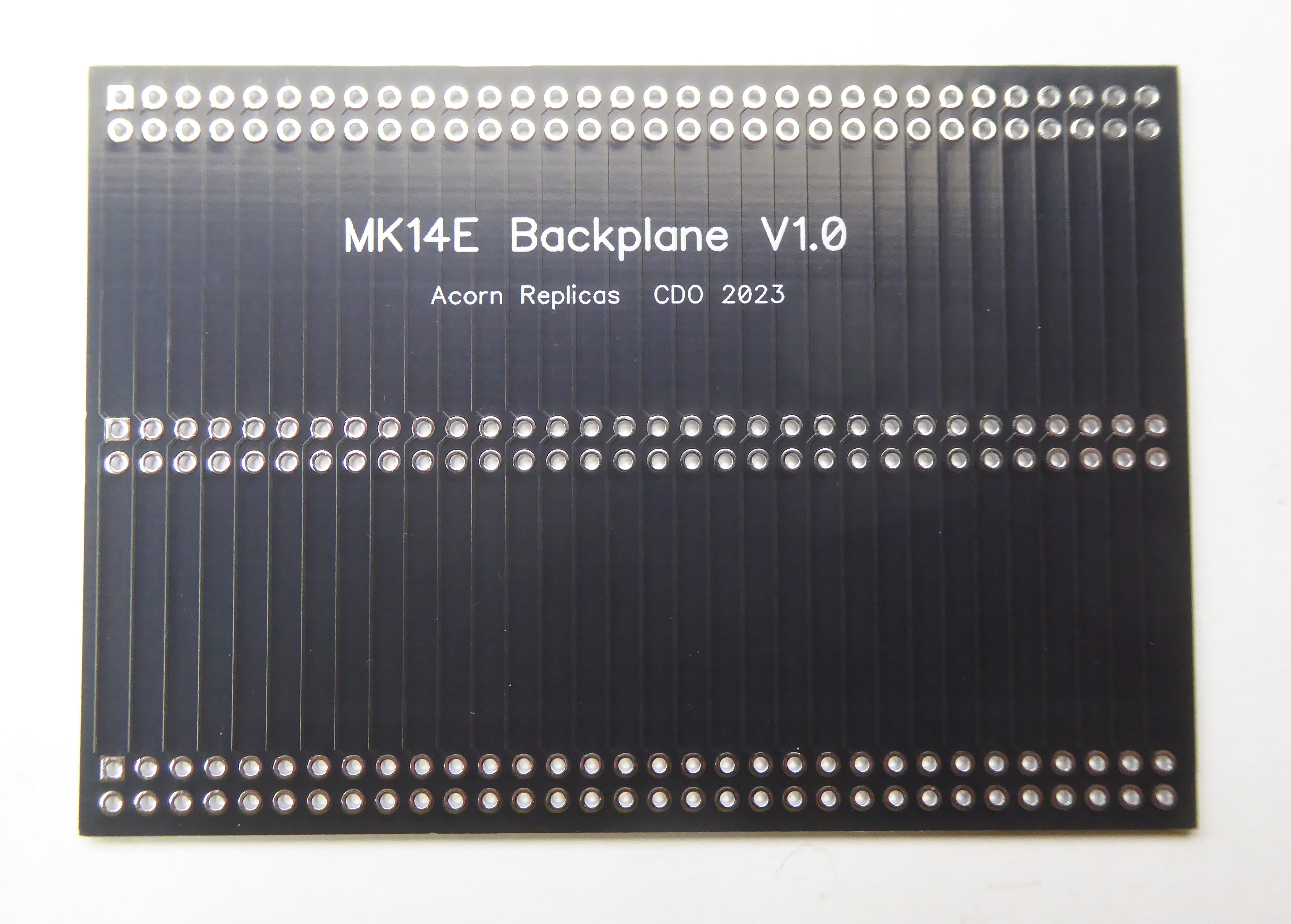
The MK14E Backplanes are a simple 3-slot or 4-slot designs using DIN41612 64-way A/B connectors, sockets are on a 1" (25.4mm) pitch.
Side B follows the numbering on the original MK14 edge connector top side, except for pin 7 which was D7 and I have reallocated as EXT I/O.
Side A follows the numbering on the MK14 VDU except for those marked *. The VDU Clock input was originally on B27 which clashes with SIN on the MK14 so that has moved to A27, it then makes sense to put NWDS next to NRDS at A29 (this follows Ian Rolfe/Slothie's V5.5 schematic). It seems certain that Sinclair left A14 to A17 ready for A12 to A15 and finally I have added NRST (A26) and NENOUT (A30).
One important thing to note with regards to the MK14E Backplane is that it is not compatible with the Acorn System Backplane.
Not only does the Acorn Backplane have both A32 and B32 joined together (0V) but 0V and +5V are swapped which would be catastrophic !
| Pin No. | Side A | Description | Side B | Description |
| 1 | 0V | Power 0V | +5V | Power +5V |
| 2 | A0 | Lower 12 bits of Address Bus from processor | +5V | |
| 3 | A1 | +5V | ||
| 4 | A2 | 0V | Power 0V | |
| 5 | A3 | 0V | ||
| 6 | A4 | 0V | ||
| 7 | A5 | EXT I/O | Pulling this line disables Mainboard memory and I/O | |
| 8 | A6 | NADS | Address Strobe, when low indicates status and upper four address lines are on data bus | |
| 9 | A7 | PB6 | 8154 (IC4) Port B | |
| 10 | A8 | PB5 | ||
| 11 | A9 | PB7 | ||
| 12 | A10 | PB4 | ||
| 13 | A11 | PB3 | ||
| 14 | A12* | Upper four Address lines from Latch IC3 | PB2 | |
| 15 | A13* | PB1 | ||
| 16 | A14* | PB0 | ||
| 17 | A15* | PA7 | 8154 (IC4) Port A | |
| 18 | D0 | Data Bus | INTR | |
| 19 | D1 | PA6 | 8154 (IC4) Port A | |
| 20 | D2 | PA0 | ||
| 21 | D3 | PA5 | ||
| 22 | D4 | PA1 | ||
| 23 | D5 | PA4 | ||
| 24 | D6 | PA2 | ||
| 25 | D7 | PA3 | ||
| 26 | NRST* | System Reset (active low) | SENSEA | Sense A condition input to processor can also be used as interrupt input |
| 27 | XOUT* | Processor Xtal oscillator output (4MHz) | SIN | Serial Input to processor E-register |
| 28 | NRDS | Read Data Strobe, data read on trailing edge | SENSEB | Sense B condition input to processor, |
| 29 | NWDS* | Write Data Strobe, when low indicates valid data on bus | SOUT | Serial Output from processor E-register |
| 30 | NENOUT* | High when processor is using the bus | FLAG0 | Flag 0 output from processor |
| 31 | NENIN | Enable Input, when low processor can access bus | FLAG2 | Flag 2 output from processor |
| 32 | +5V | Power +5V | FLAG1 | Flag 1 output from processor |
There are two versions of MK14E Backplane:
a 3-slot backplane that sits at right angles to the MK14E Mainboard, plug-in boards sit neatly above the Mainboard
a 4-slot 'Flat' backplane that sits inline with the MK14E Mainboard, plug-in boards sit vertically providing access to the Mainboard
The 3-slot backplane simply takes three straight 64-way A/B DIN sockets. The 4-slot backplane is a little different, it requires a right angle 64-way socket for connection to the Mainboard and then up to three 64-way straight sockets for plug-in boards. The boards are supported by 3D printed card guides. Unfortunately the VDU switch clashes with the 80mm long card guides so I have had to make a shorter 50mm guide for that position ! The files for printing the guides are here:
Schematics
Bill Of Materials
Blank PCBs

%20PCB.jpg)