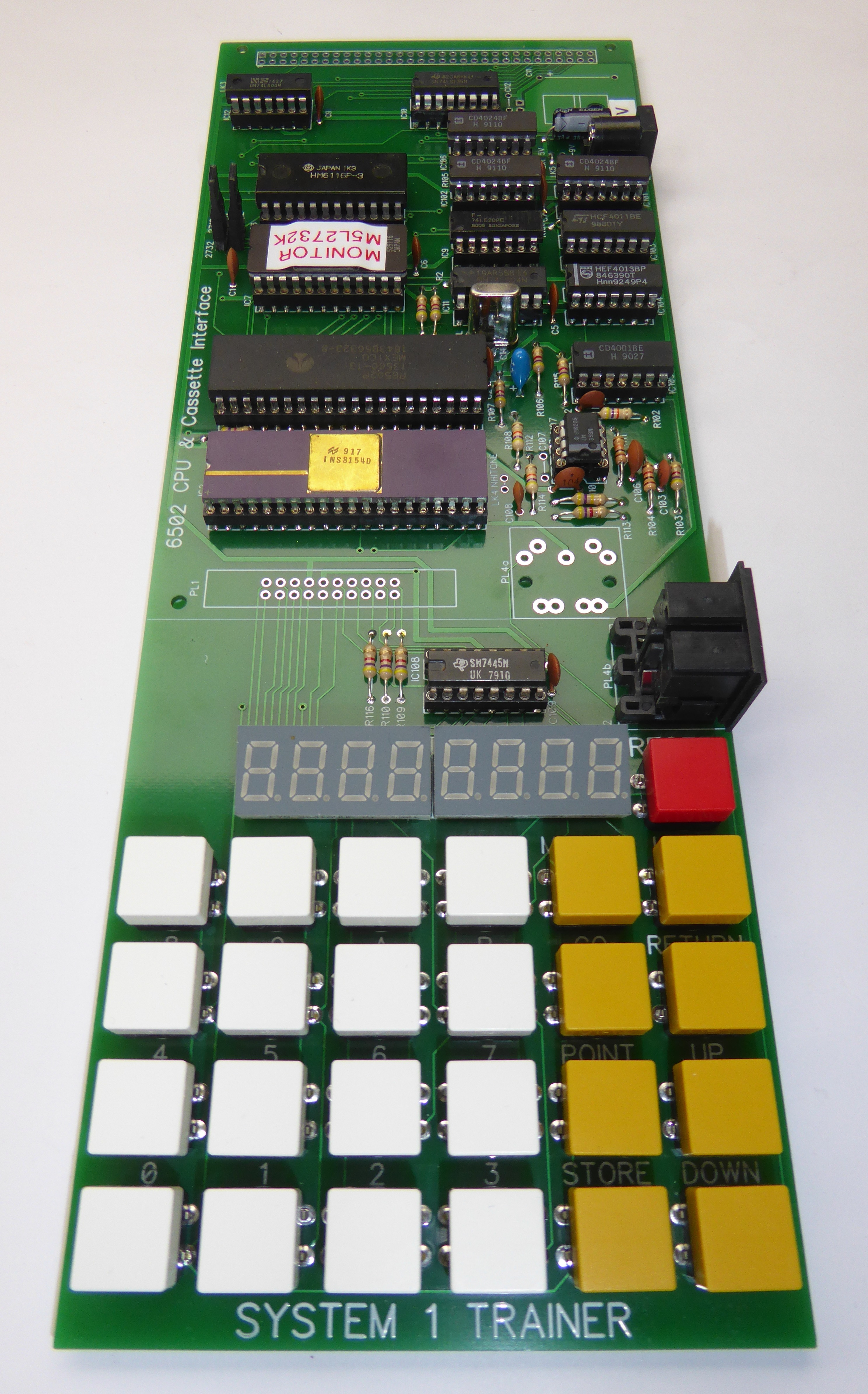

Although originally designed for the Centre for Computing History as an educational tool the System 1 Trainer is an ideal starter project and an excellent introduction to the world of real programming !
The original Acorn System 1 documentation is very good and provides useful guidance on the assembly process that is applicable to this project as well: Acorn System 1 Technical Manual. I would suggest starting by reading that and then refer to my more specific information below.
Tools Required
Not many tools are required for this project - a decent electronic soldering iron, a pair of cutters & long nose pliers and some solder ! (I would recommend sticking with good old leaded solder rather than the lead free stuff as the solder flows much better for hand soldering.)
A voltmeter will be useful for e.g. checking the power supply.
Order of Build
Here is a suggested order in which to load the components:
IC sockets - I fit these by dropping them into the PCB and placing a piece of board over the sockets and then inverting the whole thing, I then solder two diagonal corner pins on each socket so that the socket are held in place, I then go round and check each socket is seated correctly before soldering the rest of the pins
Resistors - carefully bend the legs to fit the board
Capacitors - be sure to fit C5 and C108 the correct way around !
Regulator - if required (see below), a heat sink is not necessary, if you wish to bolt it to the PCB then an insulator is not required either
Wire Links - you can use cut off component legs to make the links, see below for which links to fit
Key switches - the OMRON switches can just be push fit to start with and soldered in once you know the board works
Sockets - for power & cassette and fit the Crystal
Display - I have slightly angled the displays by raising the top edge
Feet - stick the feet on the underside of the PCB
IC's - finally fit the IC's taking care not to bend the legs, all the IC's are the same way around except the processor IC1, be sure to fit the 6502 the other way around to the other ICs !
EPROM Choices
You can fit either a 2716 or 2732 EPROM and this is selected by Links LK1 and 2.
The kit is provided with a 2732 EPROM so fit the links in the two holes to the left (nearest to the display).
Power Supply Choices
The board can be powered from either a 5V supply e.g. a USB power supply or an unregulated DC supply (7 to 9V).
To power the board from a 5V supply then just fit LK5.
To power the board from an unregulated supply fit IC13 together with the three capacitors C11,12 & 13.
Please check the power supply connection before switching on !, the centre pin of PL3 is the positive.
A USB power supply can be used as a power source with the supplied USB to power jack cable.
Switching On
Before switching on its worth spending the time to inspect the underside of the board for shorts or missing solder connections. Check the 6502 is fitted the right way around.
The board draws between 200 and 250mA depending on how many display digits are lit up. If you have a bench power supply then you could initially power it from that and set the current limit appropriately, otherwise you'll just have to go for it !
When the board is powered up the processor is not reset and you'll typically just get one dot on the right hand display or garbage, press the RESET button and you should get 8 dots on the display, if you do all is looking good. By pressing MODIFY and entering an address you can then press UP and DOWN to inspect memory.
Fault Finding
If you're unlucky enough to have problems then here are some basic checks you can do:
Links - double check they are fitted correctly (do not fit LK4)
Power - check that there is 5V on the board (the correct way around !), the power connections to all the logic chips are 0V bottom left (pin 7/8), +5V top right (pin 14/16)
Reset - check the NRST line (IC1 6502 pin 40), it should be +5V going to 0V when the RESET switch is pressed
If you have a logic probe, or better still an oscilloscope, check that the processor clock is running (1MHz) - IC11 pin 8
If you get really stuck then I can offer a repair service, please drop me an email.
System 1 Trainer Kit BOM
Here's what's included in the System 1 Trainer Kit: