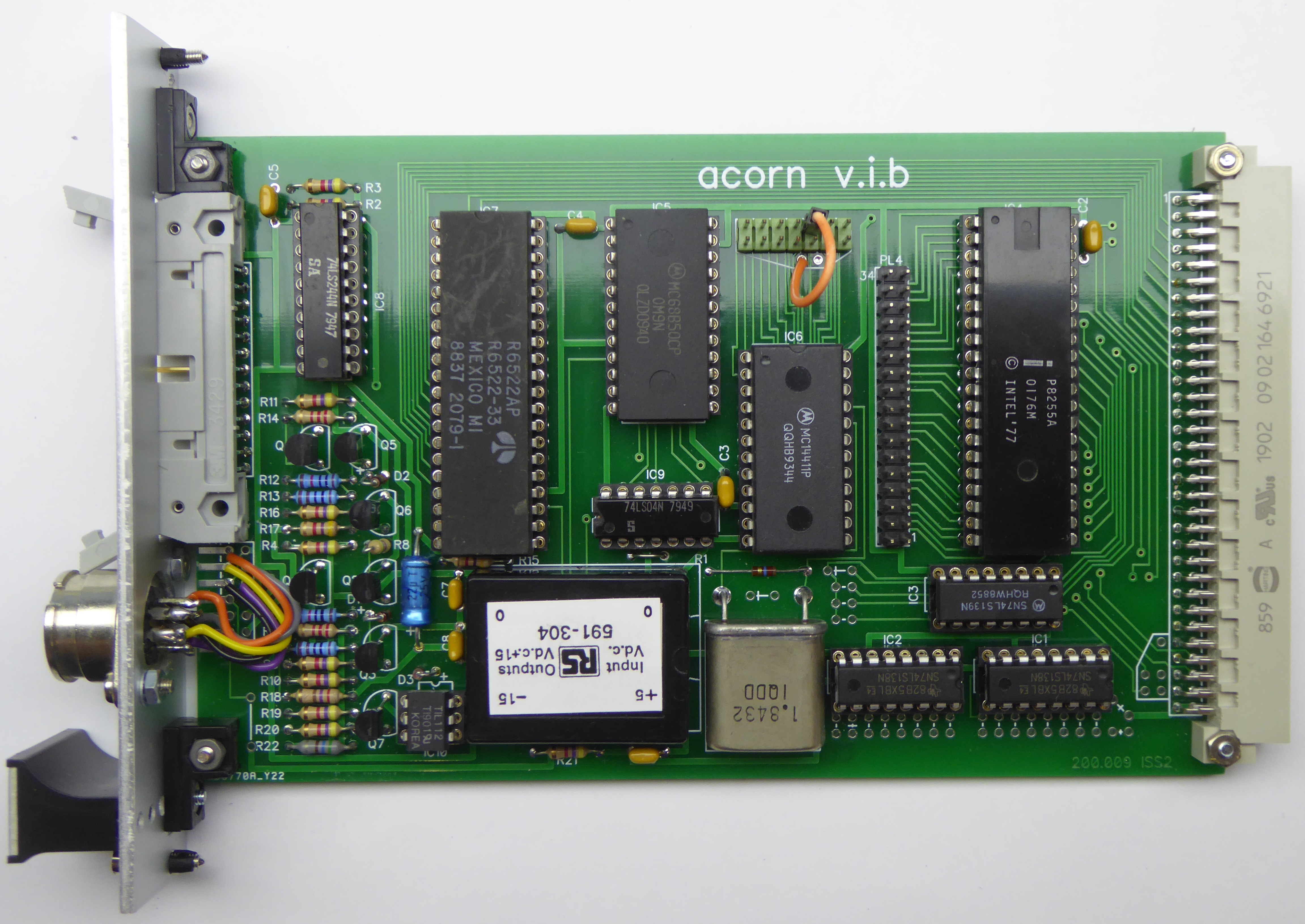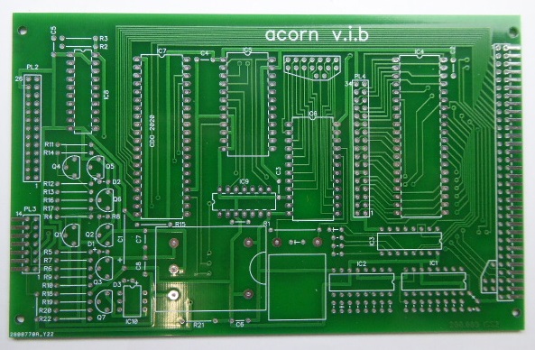

Based on the issue 3 schematic and photos of an issue 2 board.
The links have the following function:
LK1 - 20mA current loop Rx enable
LK2 - RS232 Rx enable
LK3 - VMA
LK4 - Interrupt select
LK5/5a,6,7 - Block select (not normally required)
LK8 - 20mA current loop Rx float
LK9 - Header for Baud Rate selection
PL3 Connections:
| Pin | Mode | Function |
| 1 | -12V | |
| 2 | 20mA Current Loop | TTY IN -VE |
| 3 | 20mA Current Loop | 0V |
| 4 | 20mA Current Loop | TTY IN +VE |
| 5 | 20mA Current Loop | +12V |
| 6 | 20mA Current Loop | TTY OUT -VE |
| 7 | RS232 | 0V |
| 8 | 20mA Current Loop | TTY OUT +VE |
| 9 | RS232 | CTS |
| 10 | RS232 | 0V |
| 11 | RS232 | RTS |
| 12 | RS232 | DATA IN |
| 13 | RS232 | 0V |
| 14 | RS232 | DATA OUT |
To configure the serial interface refer to the Technical Manual.
I have wired a front panel mounted 5-pin 240deg DIN socket for RS232 use as follows:
| DIN socket pin | wire to PL3 pin | Function |
| 1 | 11 | RTS |
| 2 | 14 | Data out |
| 3 | 10 | 0V |
| 4 | 12 | Data In |
| 5 | 9 | CTS |
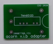
Because the DC-DC converter is no longer available I have made a small adapter board which allows the fitting of a Traco Power TMA 0512D (RS 189-6997).
Schematic
Bill Of Materials
Front Panel Drilling
Blank PCBs


Board with Adapter Board Fitted
.jpg)