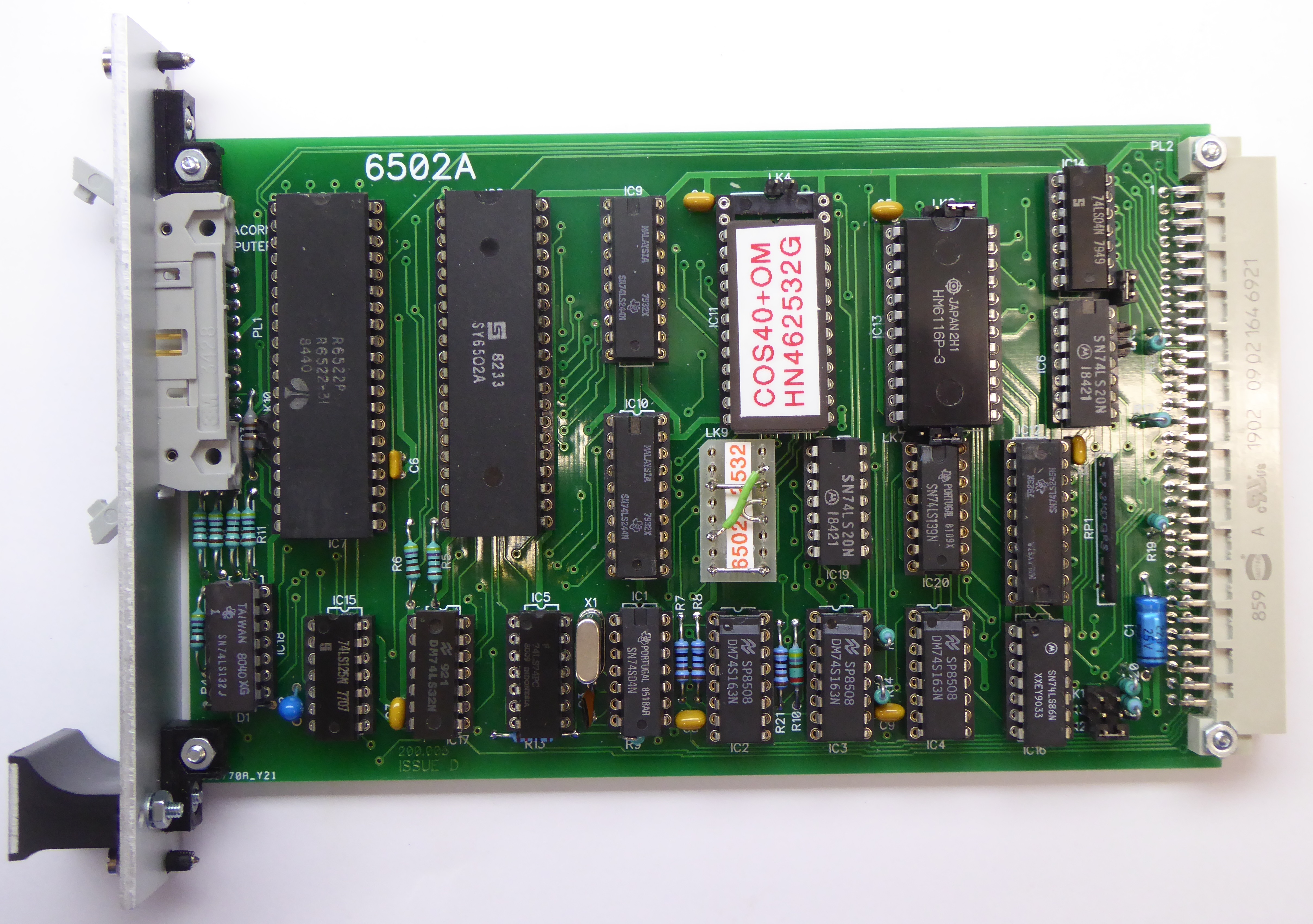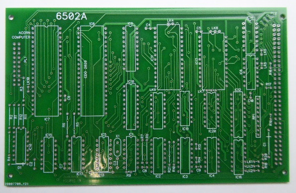

Based on the issue 1 schematic and photos of an issue C board.
The links have the following function:
LK1 - selects 3MHz clock
LK2 - selects 1MHz clock
LK3 - selects 2MHz clock
LK4 - used in conjunction with LK9 to select EPROM configuration
LK5 - selects 2K RAM
LK6 - selects 1K RAM
LK7 - used to configure IC13 for EPROM, for RAM fit towards bus connector
LK8 - used to configure IC13 for EPROM, for RAM fit towards bus connector
LK9 - selects EPROM configuration, see System 5 Handbook Part 2 Section 2 6502A CPU Board [2] (but see note below !)
LK10 - selects keyboard interrupt control, normally open
Before using the LK4/9 link settings in the System 5 Handbook it is worth checking them against the circuit for your particular EPROM. For instance fitting LK4 for a 23128/27128 as shown in Figure 8 will result in shorting A13 to +5V which is clearly wrong !
If using the board with a 40x25 VDU (Teletext) Interface Board then ensure you fit LK6 for 1K RAM and not LK5, the 2nd page of 2K RAM will clash with the VDU boards RAM.
The manual for the original Acorn board states using a 6116LP-4 SRAM however I and others have found that '6116' SRAMs don't always behave reliably in this board and recommend using an NEC uPD446C-3 in its place which seems to work fine at 1 or 2MHz (yes the photo above still shows a 6116 !).
Schematic
Bill Of Materials
Front Panel Drilling
Blank PCB
