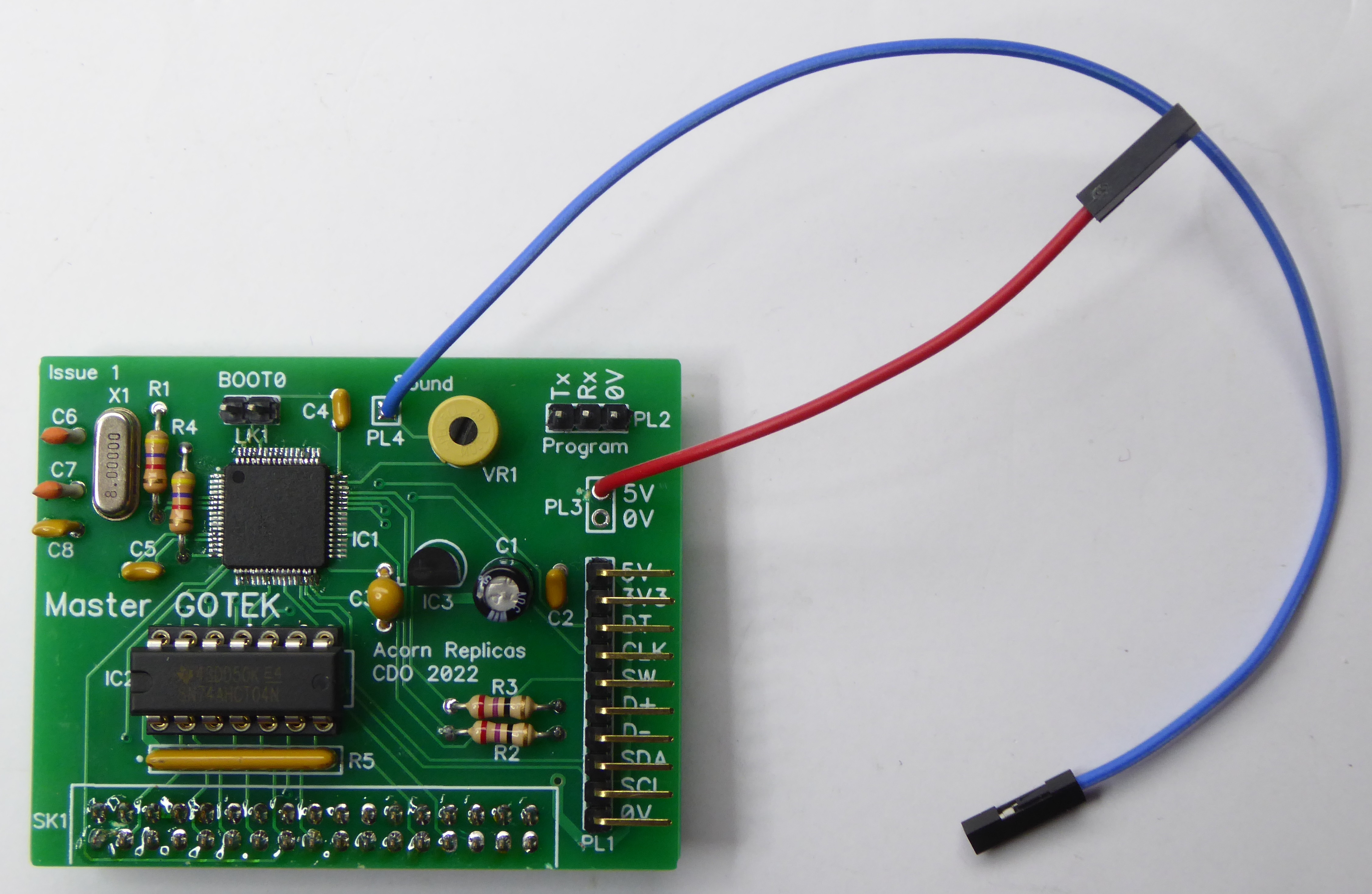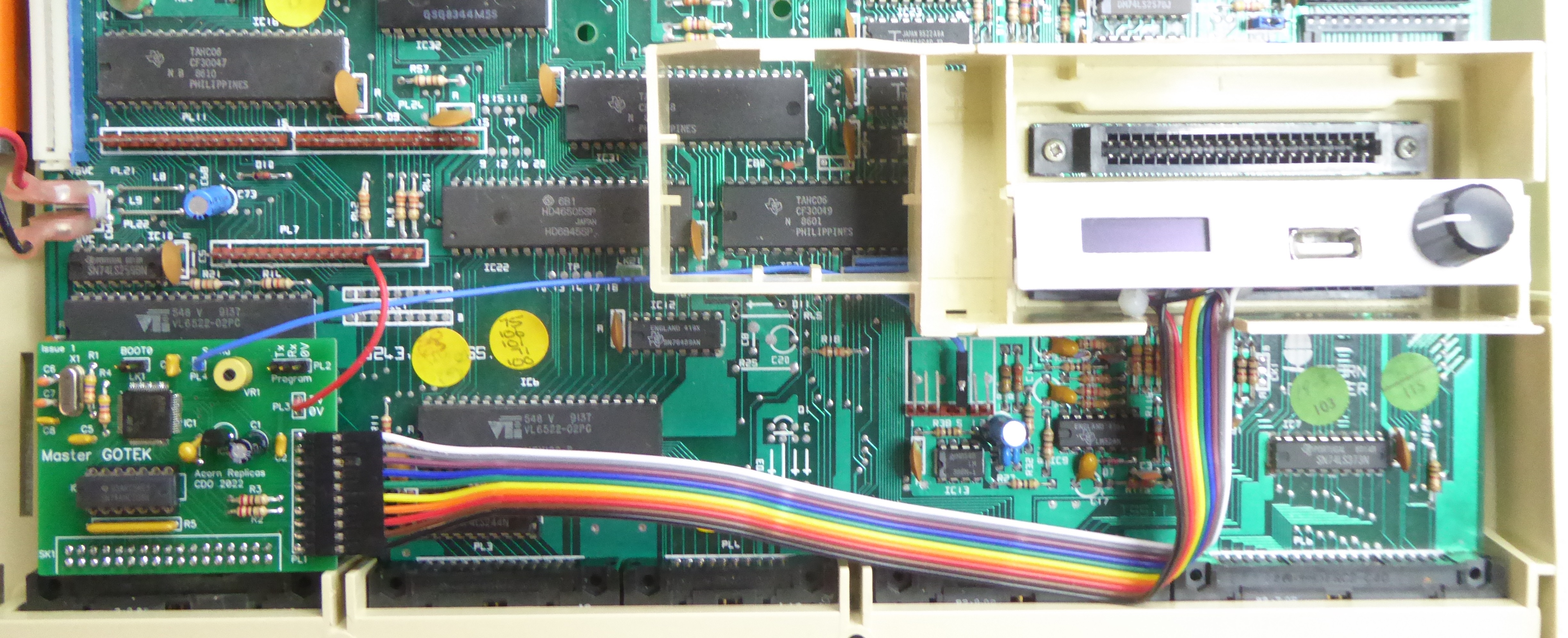

This is a spin off from the FileStore E01E FDC Board which incorporates a pair of GOTEK circuits. This is one of those circuits on a small PCB that fits inside the Master connecting to the Internal Floppy Disk interface, connector PL2. A panel fits over one of the Cartridge Slots with the USB socket, OLED Display and a Rotary Encoder.
Please note this board should not be used in conjunction with an external drive, it does not have the required open collector drivers to allow for multiple drives.

A 10-way ribbon cable is wired to PL1 taking the signals to the panel, connections are as follows:
| PL1 Pin | Signal | Connects to |
| 1 | 0V | |
| 2 | SCL | Display |
| 3 | SDA | Display |
| 4 | D- | USB |
| 5 | D+ | USB |
| 6 | SW | Encoder Switch |
| 7 | CLK | Encoder Clock |
| 8 | DT | Encoder Direction |
| 9 | +3V3 | Display |
| 10 | +5V | USB |
The Internal Floppy Disk Interface connector, PL2, is not normally fitted and so needs to have a 34-way double row header soldered in (you may find the holes are filled with solder which needs to be cleared first).
Power is taken from the unused 'Keyboard Con 2' connector, PL7 - a single wire to pin 15 provides +5V to the board, either fit a header to the PCB (PL3) or a flying wire terminated in a single DuPont type socket to plug-in to Master PL7.
The GOTEK will also produce 'floppy drive' sounds which normally go to a small piezo sounder, this signal can be routed to the 'MODEM' interface PL10, connector as follows:
| PL10 Pin | Signal |
| 1 | SPEECH |
| 2 | MAN OUT |
| 3 | A GND |
| 4 | Keyway |
| 5 | SND IN |
Again either fit a header to the PCB (PL4) or a flying wire terminated in a single DuPont type socket to plug-in to Master PL4 pin 5 'SND IN'.
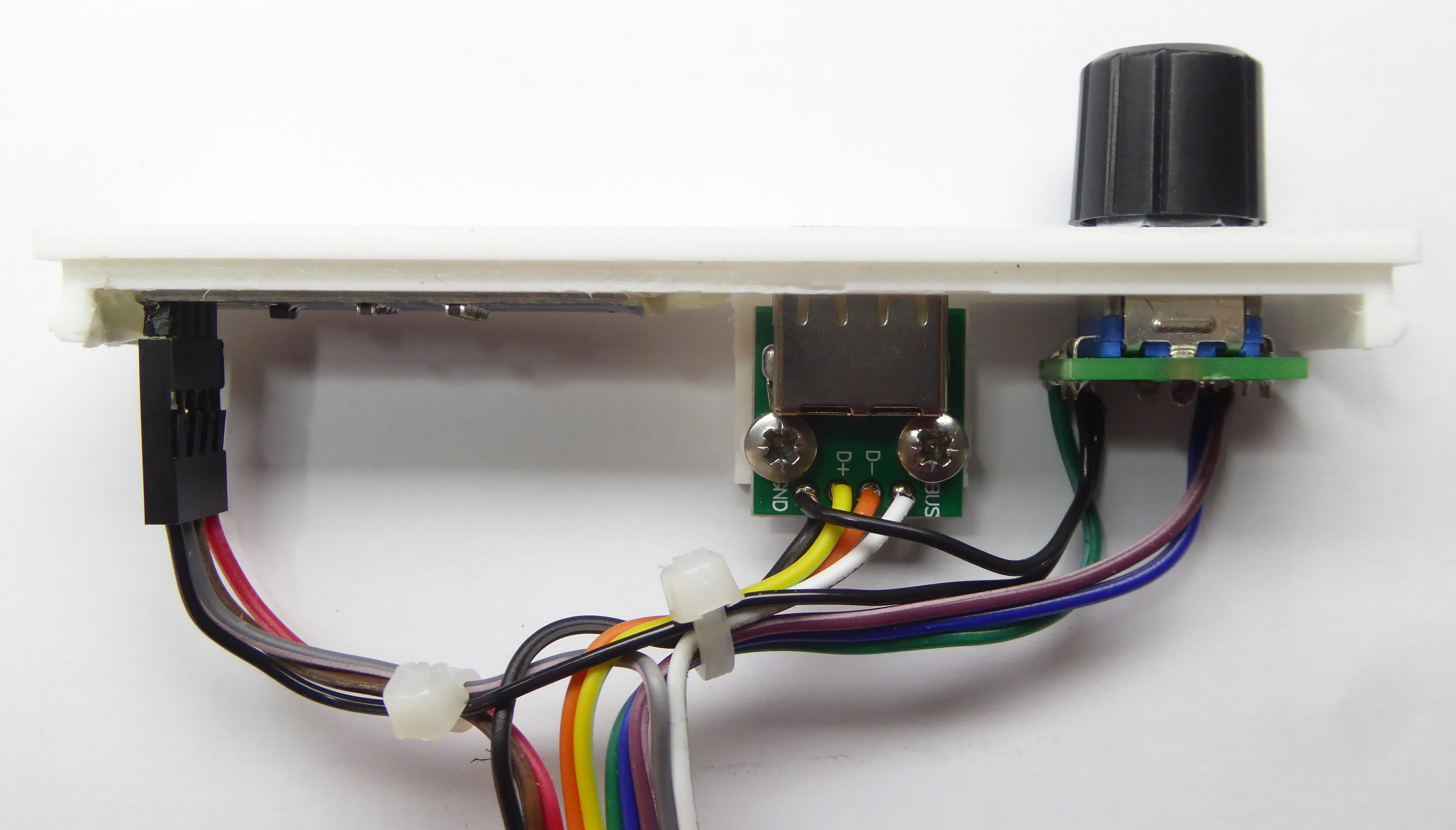
The GOTEK display, rotary encoder and USB socket can be mounted on a 3D printed panel fitted over one of the Cartridge Slots, the OpenSCAD and STL files to print your own are included below.
I cut a slot at the front of the cartridge/speaker surround so that the ribbon cable could run into the cartridge space.

The connections to the Front Panel items are as follows:
USB Socket
| Pin | Signal | Connect to PL1 pin |
| 1 | +ve | 10 (+5V) |
| 2 | D- | 4 (D-) |
| 3 | D+ | 5 (D+) |
| 4 | -ve | 1 (0V) |
OLED Display
| Pin | Signal | Connect to PL1 pin |
| 1 | GND | 1 (0V) |
| 2 | Vcc | 9 (+3V3) |
| 3 | SCL | 2 (SCL) |
| 4 | SDA | 3 (SDA) |
Rotary Encoder
| Signal | Connect to PL1 pin |
| Switch | 6 (SW) |
| Switch Ground | 1 (0V) |
| Clock | 7 (CLK) |
| Ground | 1 (0V) |
| Direction | 9 (DT) |


Assembly is a bit fiddly as the panel needs to be fitted to the computer lid first and is connected to the PCB with the keyboard removed, then the keyboard is refitted whilst holding the lid up.
The STM32 processor is most easily programmed via its serial port (PL2) using an FTDI USB converter (must be 3V3) and the STM32 Cube Programmer application which can be found here https://www.st.com/en/development-tools/stm32cubeprog.html. To initiate programming the BOOT0 link (LK1) should be fitted. If you have an OLED display connected this must be disconnected during programming or the processor will think you are using SPI rather than serial. The GOTEK Flash Floppy firmware can be found here https://github.com/keirf/FlashFloppy/wiki.
Connections to the serial port for programming are as follows:
Pin 1 0V connects to FTDI 0V Pin 1/Black wire
Pin 2 RxD connects to FTDI TxD Pin 4/Orange wire
Pin 3 TxD connects to FTDI RxD Pin 5/Yellow wire
I've had a couple of processors which refused to connect via the bootloader using the serial connection but they connected fine using an ST-LINK and the JTAG/SWD interface. To do this you will need to make a couple of extra connections to the processor (IC1): SWCLK pin 49 and SWDIO pin 46, I have added these as pads on later boards, then programming uses the same Cube Programmer application.
Schematic
Bill Of Materials
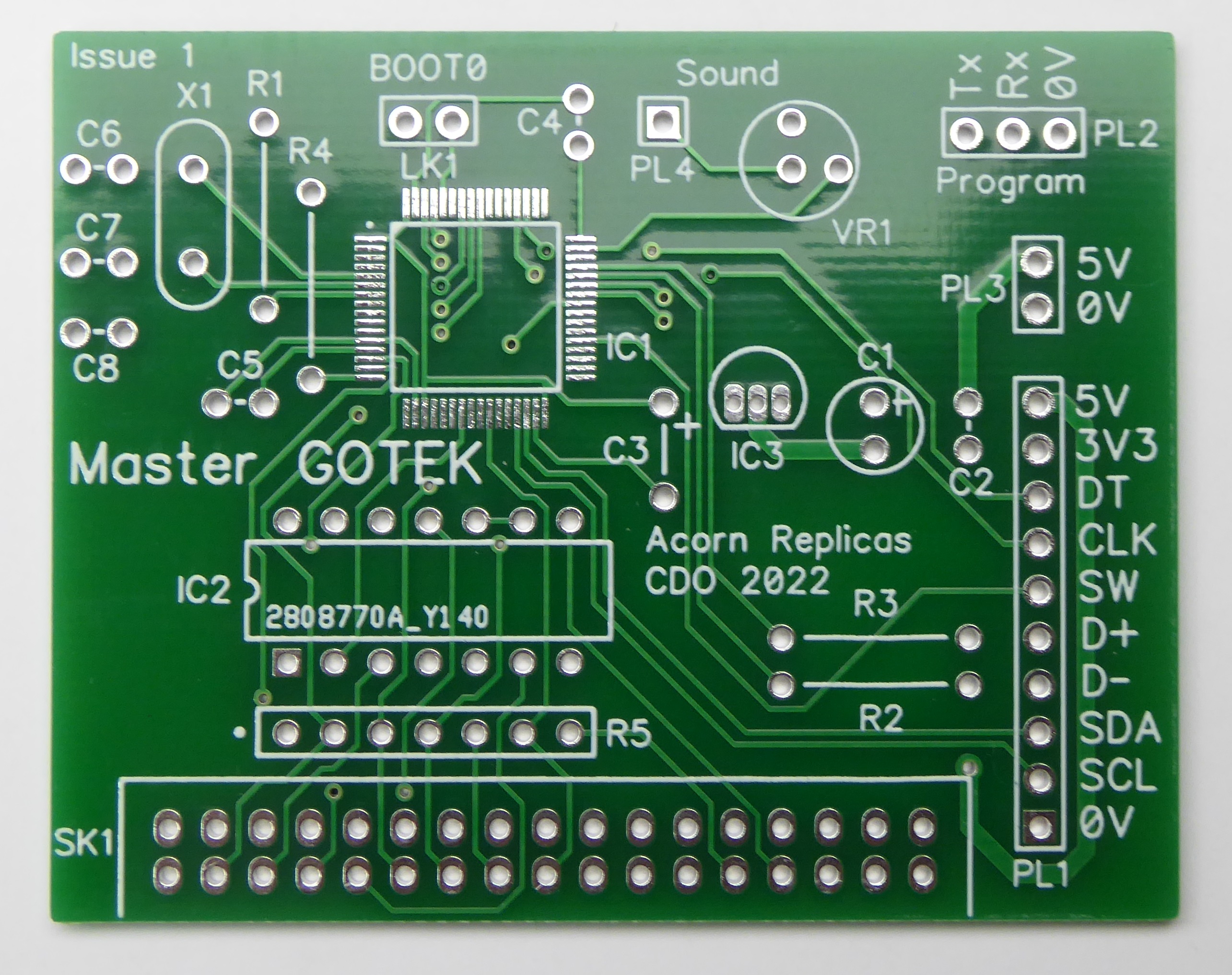
PCB

Front Panel Files