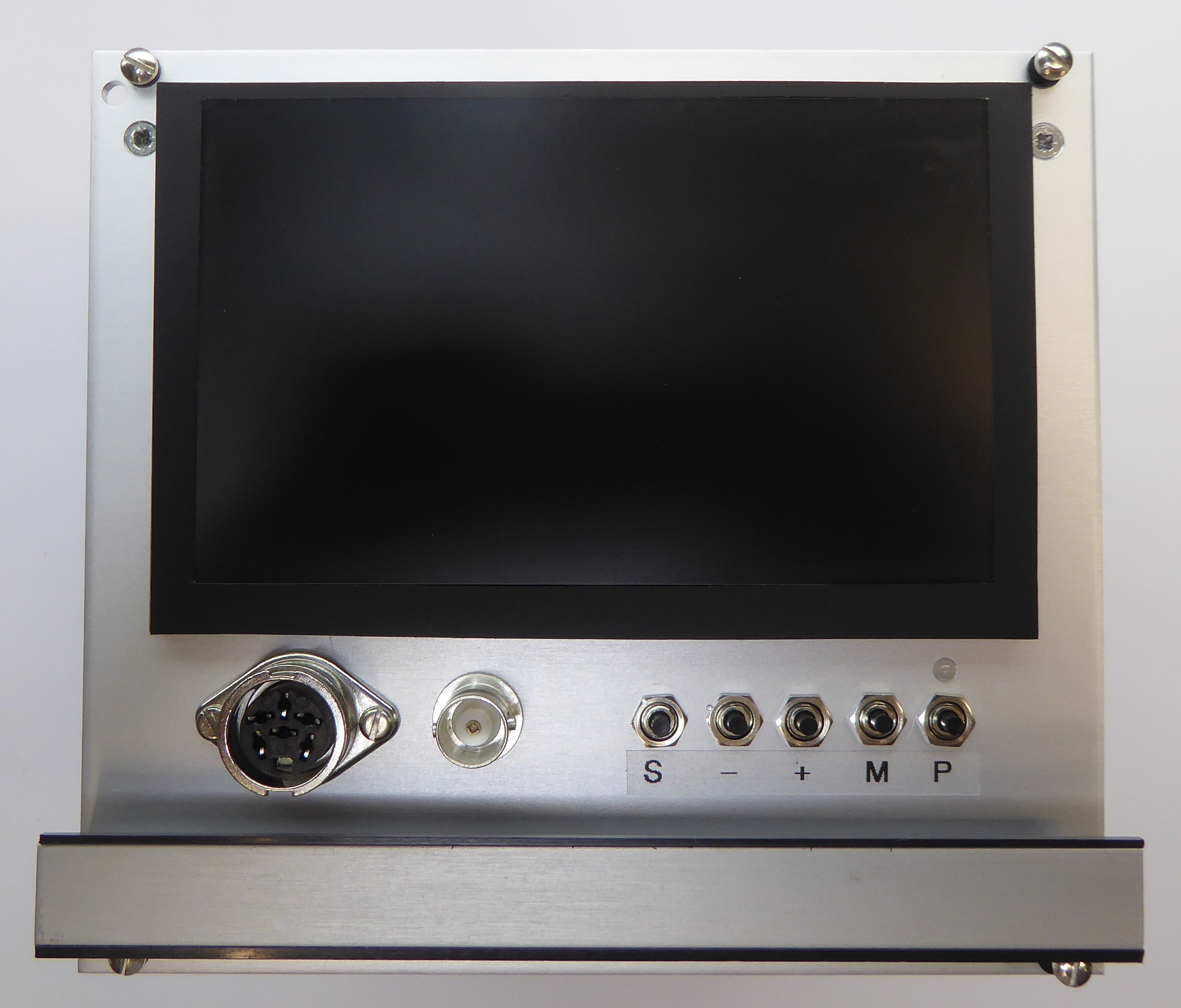

The idea for this module came about when I saw the Control Universal Card Frame Mounting CRT Monitor. This modern version incorporates a 5" TFT LCD display (EastRising ER-TFTV050-4). The display comes with its own driver board which can accept HDMI, RGB or video. I have also included a GBS8200 RGB to VGA converter so that the unit can accept RGB (BBC computer standard 6-way DIN socket) or video (via the BNC) from the System Computer video cards.


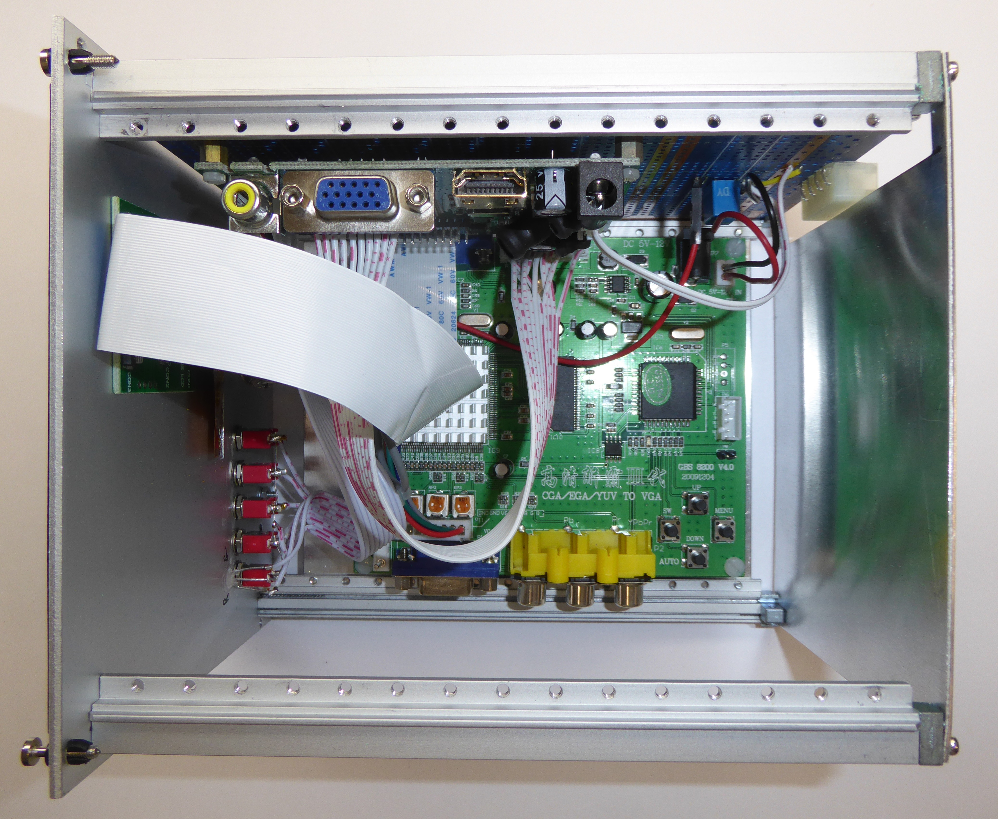
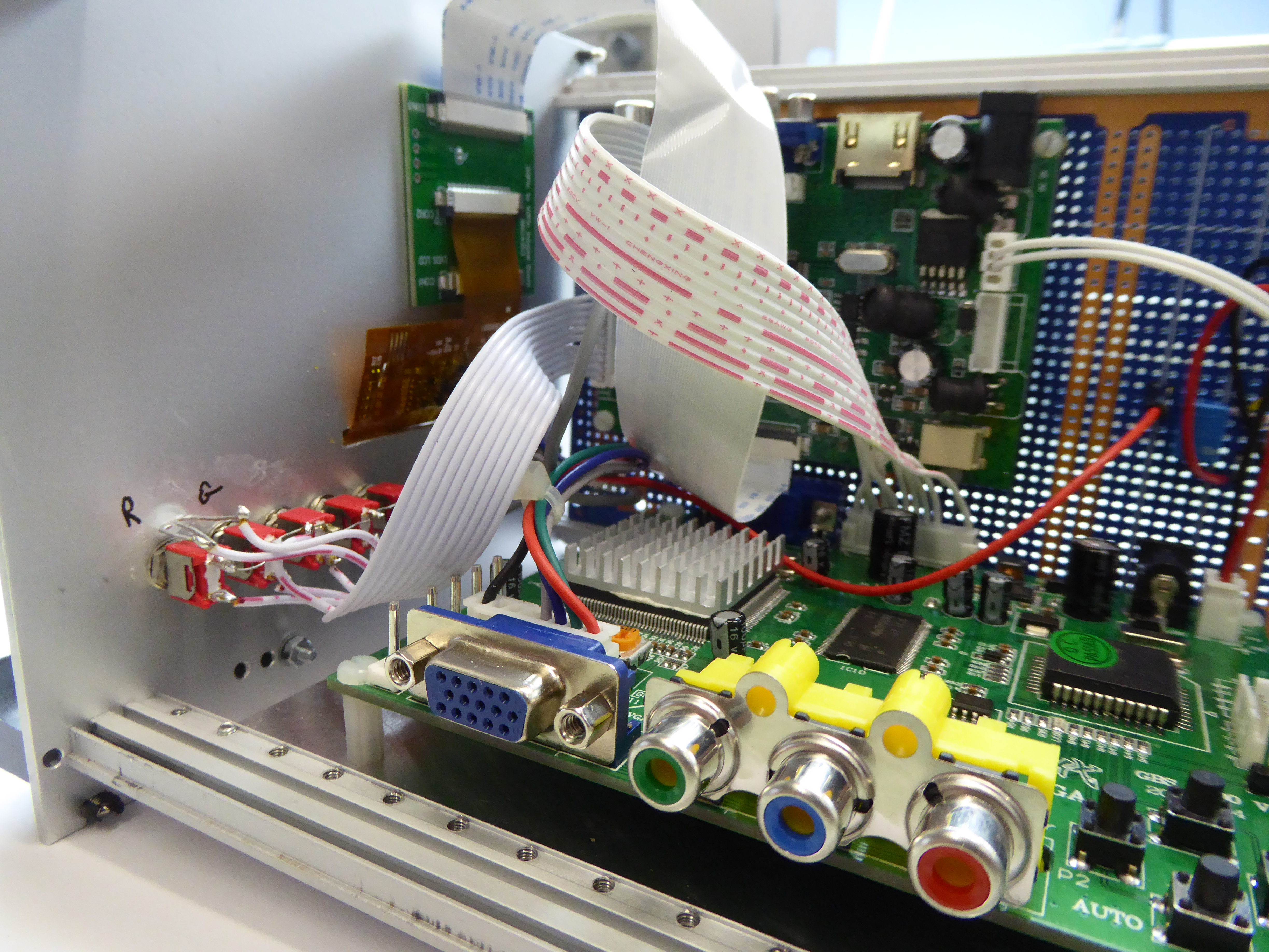
The monitor is built into a 28HP wide plug-in module, not a standard size so this has been made by cutting down a 42HP module. The display is fixed to the front of the module, its driver board is mounted on a recycled Eurocard prototyping card on the left hand side of the module and the RGB Converter is mounted on a baseplate in the bottom of the module. Both boards have configuration menus which are accessed through 4 or 5 push buttons. I have fitted 5 small push switches on the front panel to provide access to the LCD driver module menus, I expect that once set up the only button required is the one that selects input source, in this case Video or RGB. The RGB converter buttons are less likely to be required but the originals can still be accessed by sliding the module out part way.
Both boards can be powered from between 5 and 12V, I chose to use 12V as the current increases to over 1A at 5V and is only about 400mA at 12V (same power of course !). The LCD driver board is permanently powered, the GBS8200 only needs to be powered when required to convert RGB so that is powered via a small relay which is switched by the SCART control line on the BBC standard RGB 6-pin DIN socket.
A number of cable assemblies are required to interconnect the parts:
The GBS8200 module comes with cables that plug into the 2-pin power and 8-pin RGB sockets.
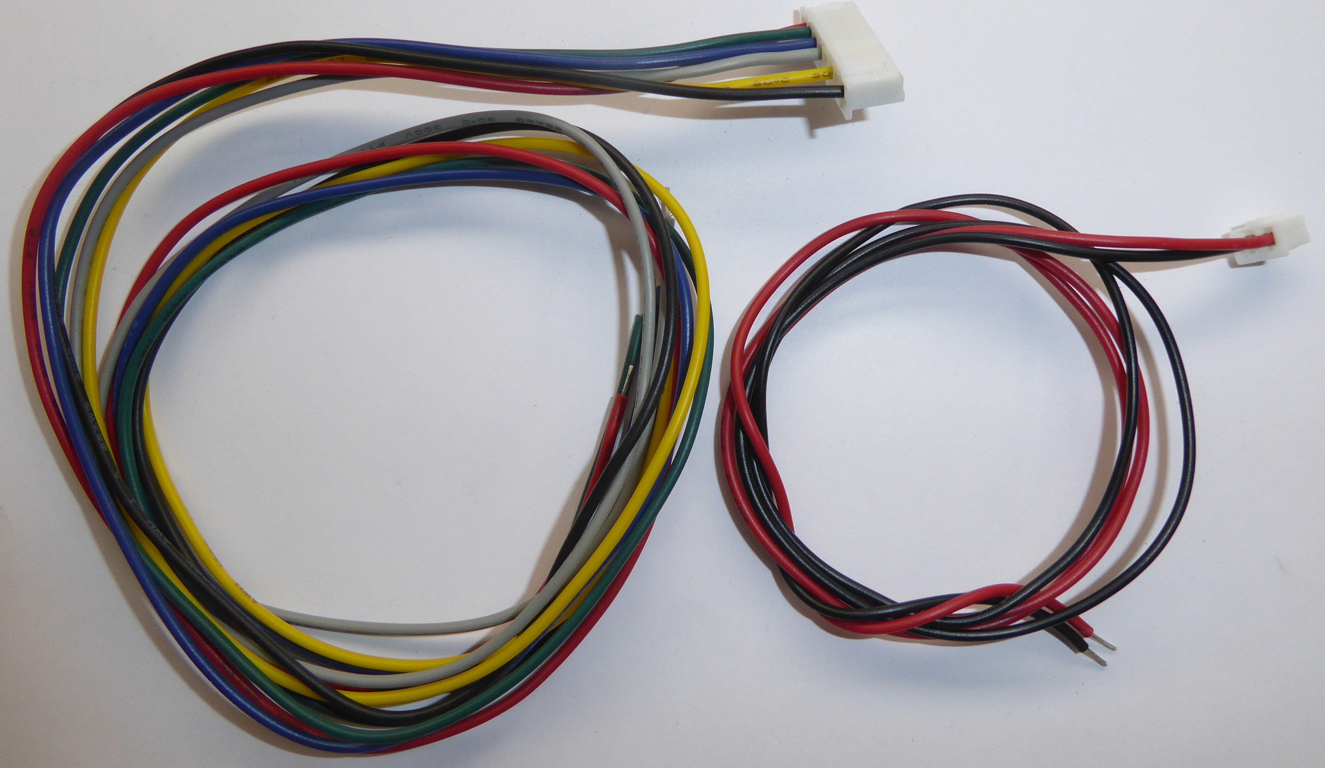
The power cable plugs into P9 and is wired directly to the relay circuit, see below. The RGB cable plugs into P11 and is wired to the front panel DIN socket.
The TFT kit I purchased didn't come with the VGA cable shown in the photo above. The two boards are interconnected by VGA, to make this connection I used a ready made 12-way JST PH 2.0 cable and carefully removed the pins from one end and refitted them to match the connections of the two boards:
| TFT Driver Board (J4) |
Cable | GBS8200 (P12) |
 |
| 1 | Red | ||
| 2 | 0V | ||
| 0V | 3 | Green | |
| Blue | 4 | 0V | |
| 0V | 5 | Blue | |
| Green | 6 | 0V | |
| 0V | 7 | H | |
| Red | 8 | V | |
| 0V | 9 | 0V | |
| H | 10 | ||
| V | 11 | ||
| 0V | 12 | 0V |
The front panel video connection is wired from the front panel mounted BNC socket to the LCD driver board socket (J5) and requires a 5-pin JST PH 2.0 connector.
Power for the driver board is viaa 4-pin JST PH 2.0 connector (J3), the front panel switches and LED are connected again with an 10-pin JST PH 2.0 cable to J6.
The display is simply glued with adhesive tape to the front panel and the cable fed through a slot, a piece of black adhesive backed plastic serves as a bezel. The small adapter board is similarly taped to the inside of the front panel.
I have recycled an old Eurocard prototyping board to attach the driver board, relay and power connector (a standard 5.25" floppy socket).
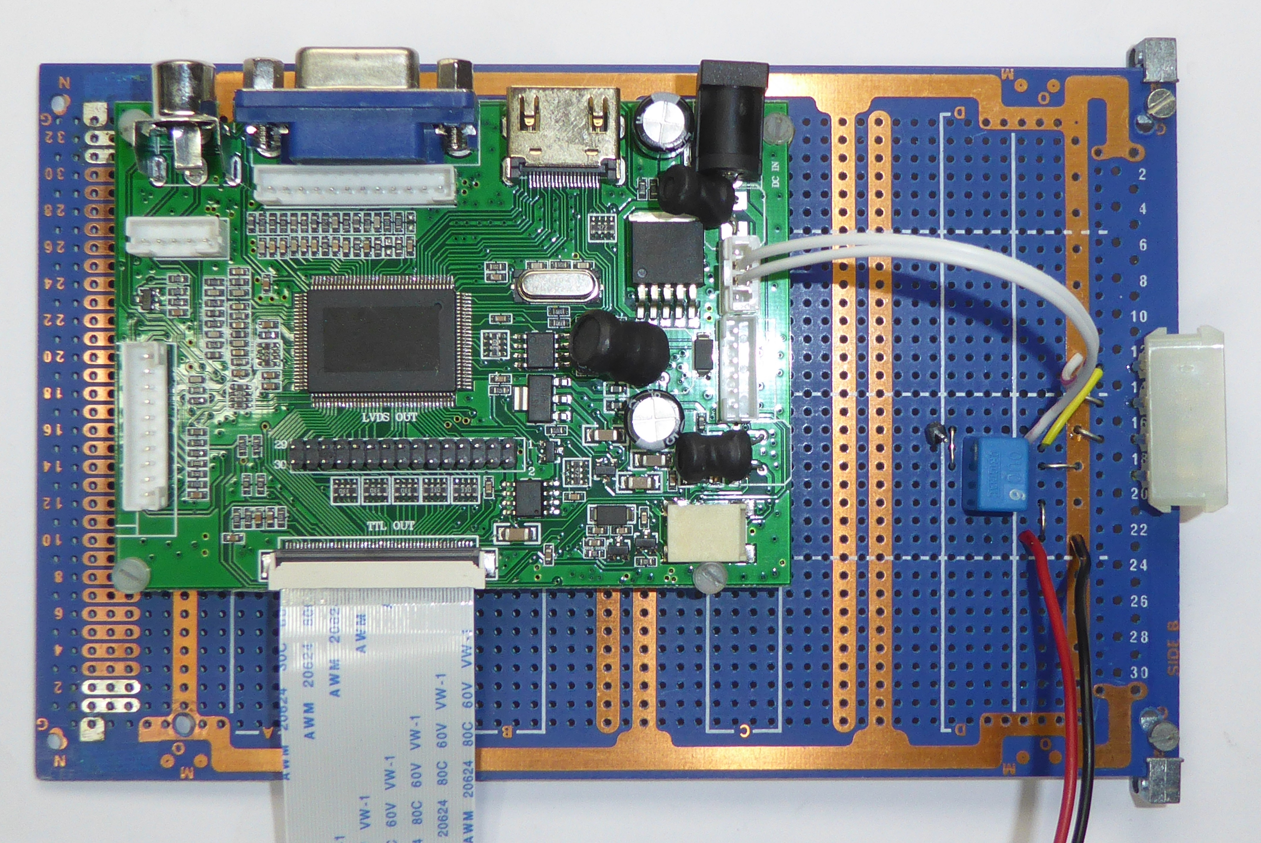
Side View
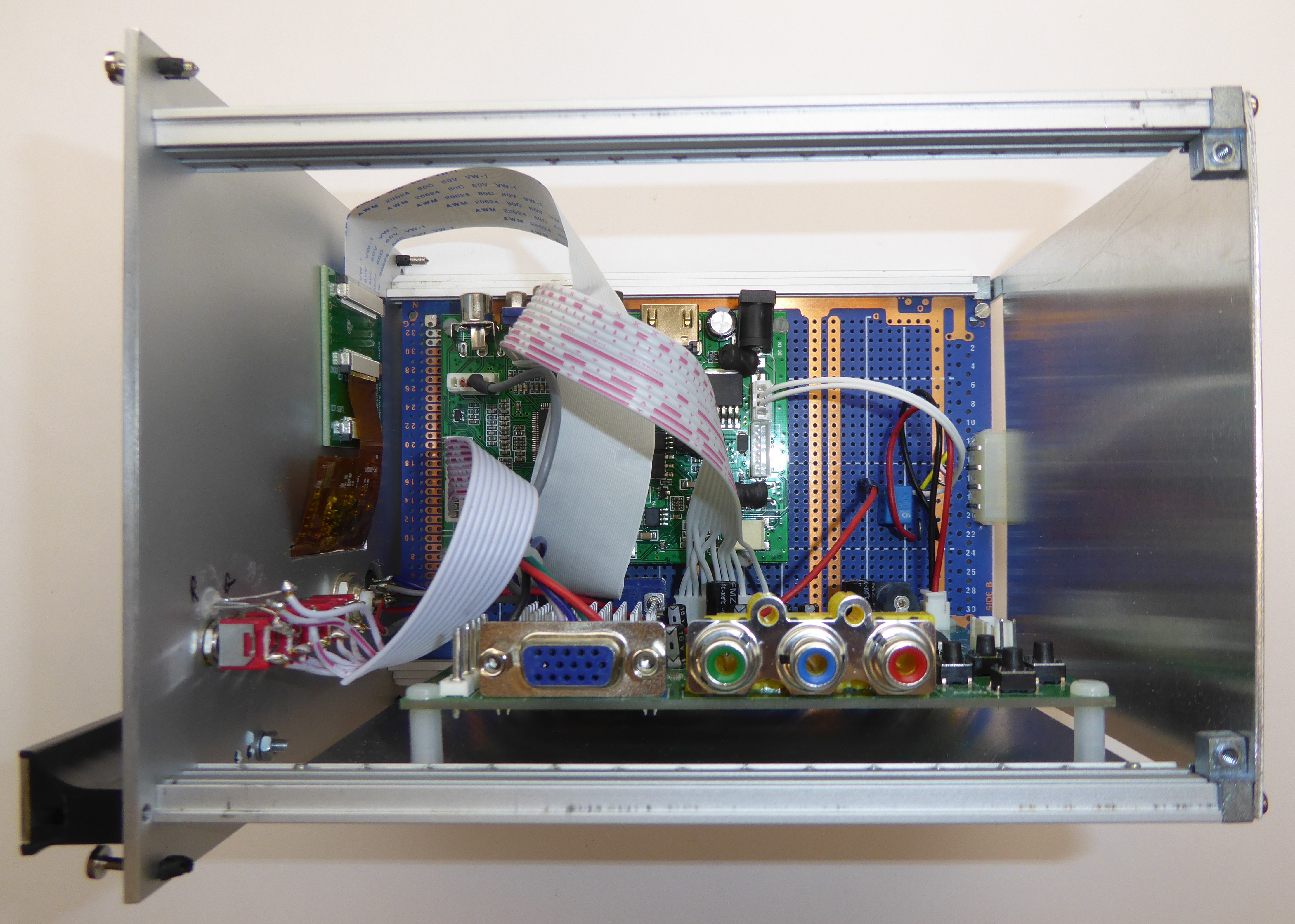
Top View
Internal View
Bill Of Materials
Front Panel Drawings