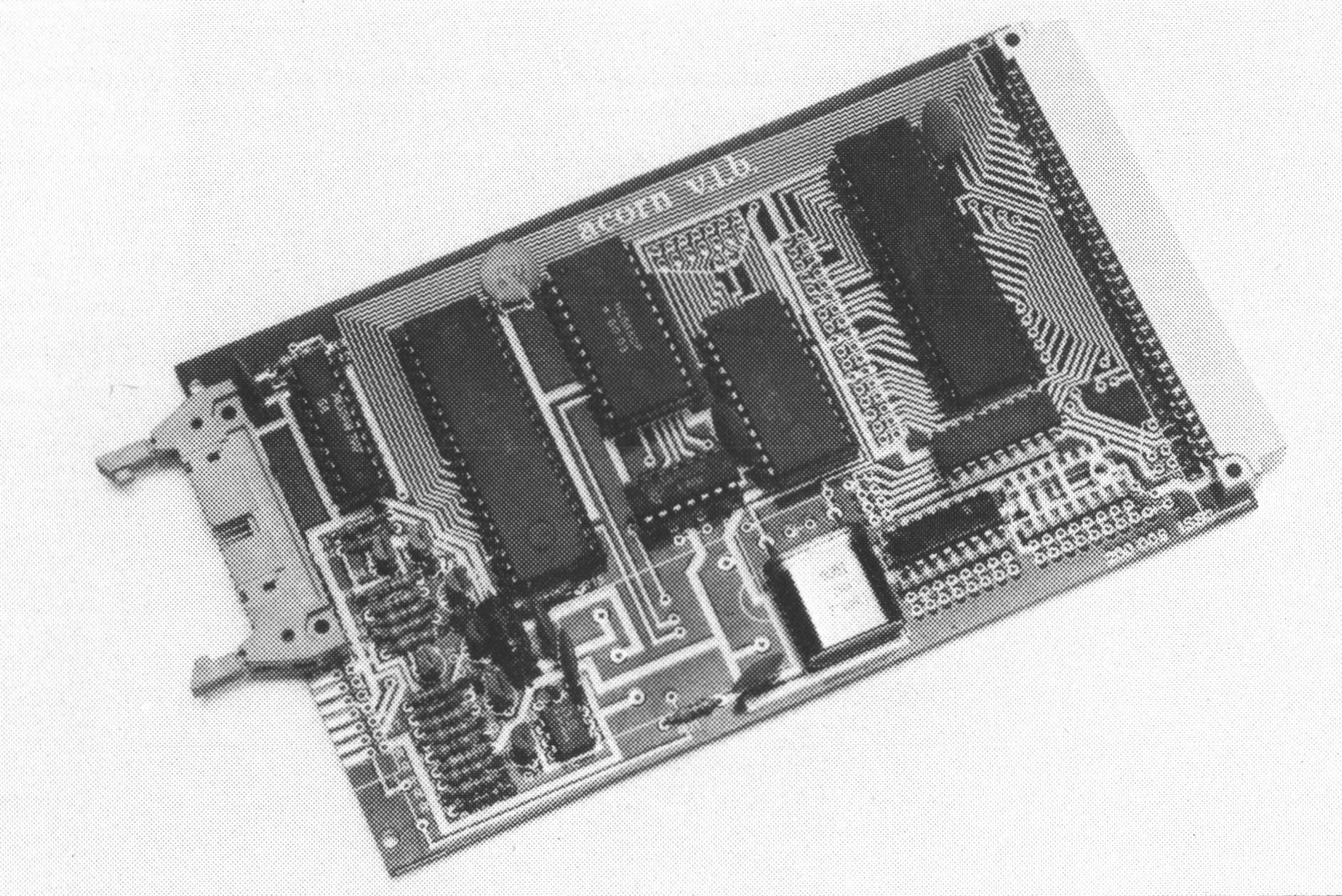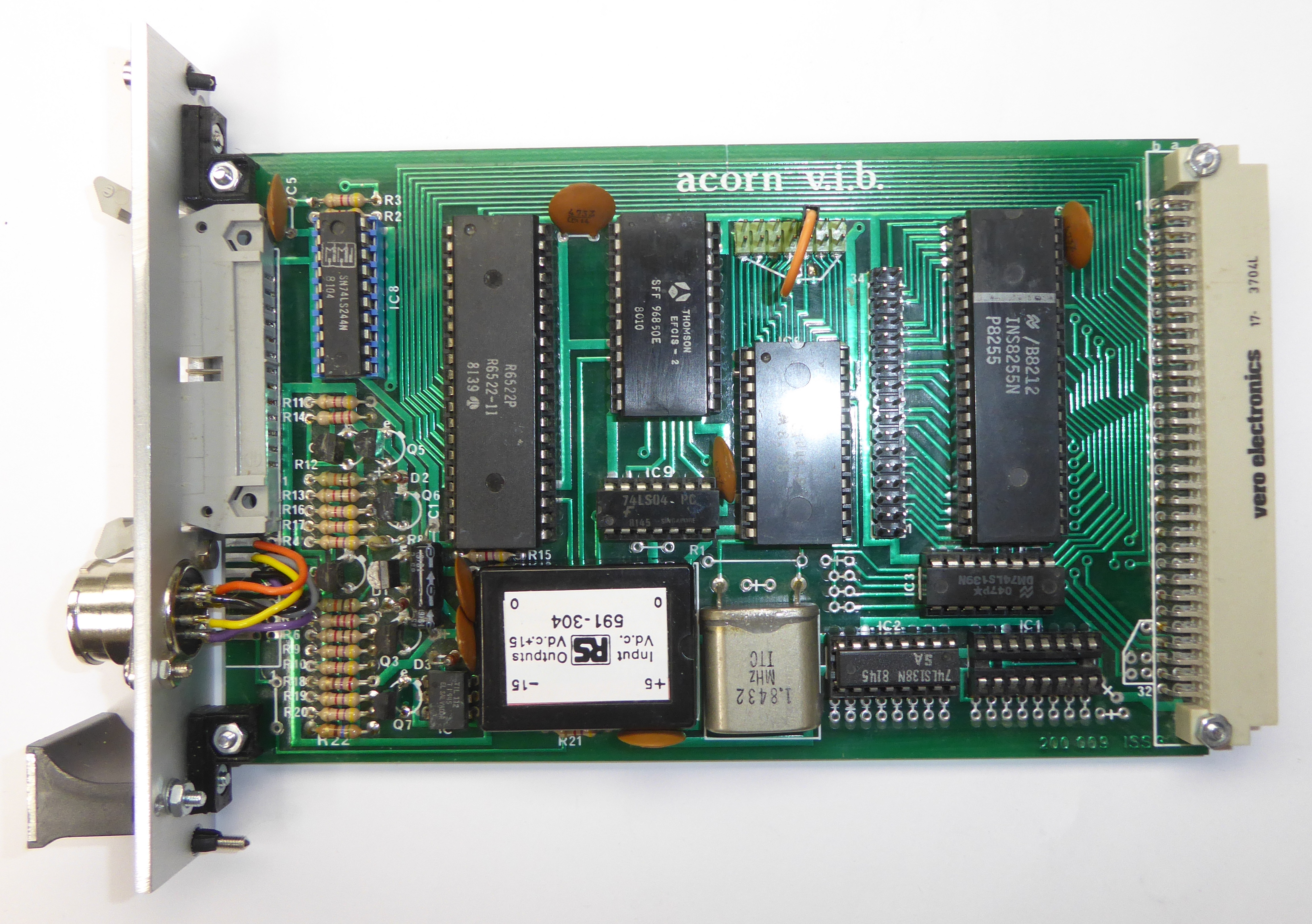

"This board connects to the standard Acorn bus and provides
interfaces via the three integrated circuits listed below:
6522
This device has two, ten bit parallel, TTL level I/O ports
(i.e. 8 individually programmable data bits plus 2 control bits each) and a pair
of interval timers for providing real time interrupts. One port connects to side
B of the bus, the other going via a high current buffer to the front of the
board where a 26 way connector may be fitted. This connector is pin compatible
with the Centronics, Anadex and other printers.
INS 8255
This device provides three ports of TTL level parallel I/O
via a 34 way connector.
Two of these ports are 8 bits wide and may each be
programmed to be either all input or all output whilst the third port which is
also 8 bits wide, has its direction programmed in two groups of 4 bits.
MC6850
This device provides serial interfacing together with an
MC14411 bit rate generator IC and a 1.8432 MHz crystal which enable standard
baud rates in the range 75 to 9600 baud to be selected. Edge connectors on the
front of the board provide a 20mA Teletype connection and a RS232C connection.
The 20mA serial input is via an optical isolator giving ground isolation between
interconnected Acorn systems.
The RS232C interface requires a ±12 volt supply which may
either be connected via the front edge connector or can be provided by an
on-board 5v to ±12V converter module. The serial data is also available at TTL
levels and the control lines "Clear to Send" and "Request to Send" are available
at RS232C or TTL.
As supplied the board is memory mapped at page OC (i.e. in
block zero) and the buffered 6522 port provides connection for the system
printer as required by both COS and DOS. Program examples of inputting and
outputting serial data will be supplied so that users can write software to use
these as peripheral terminals.
With the addition on board of a 74LS138 the board can be
mapped in any block allowing many boards to be used as experimental interfaces
or for provision of extra printers etc.
Documentation:
Photos:
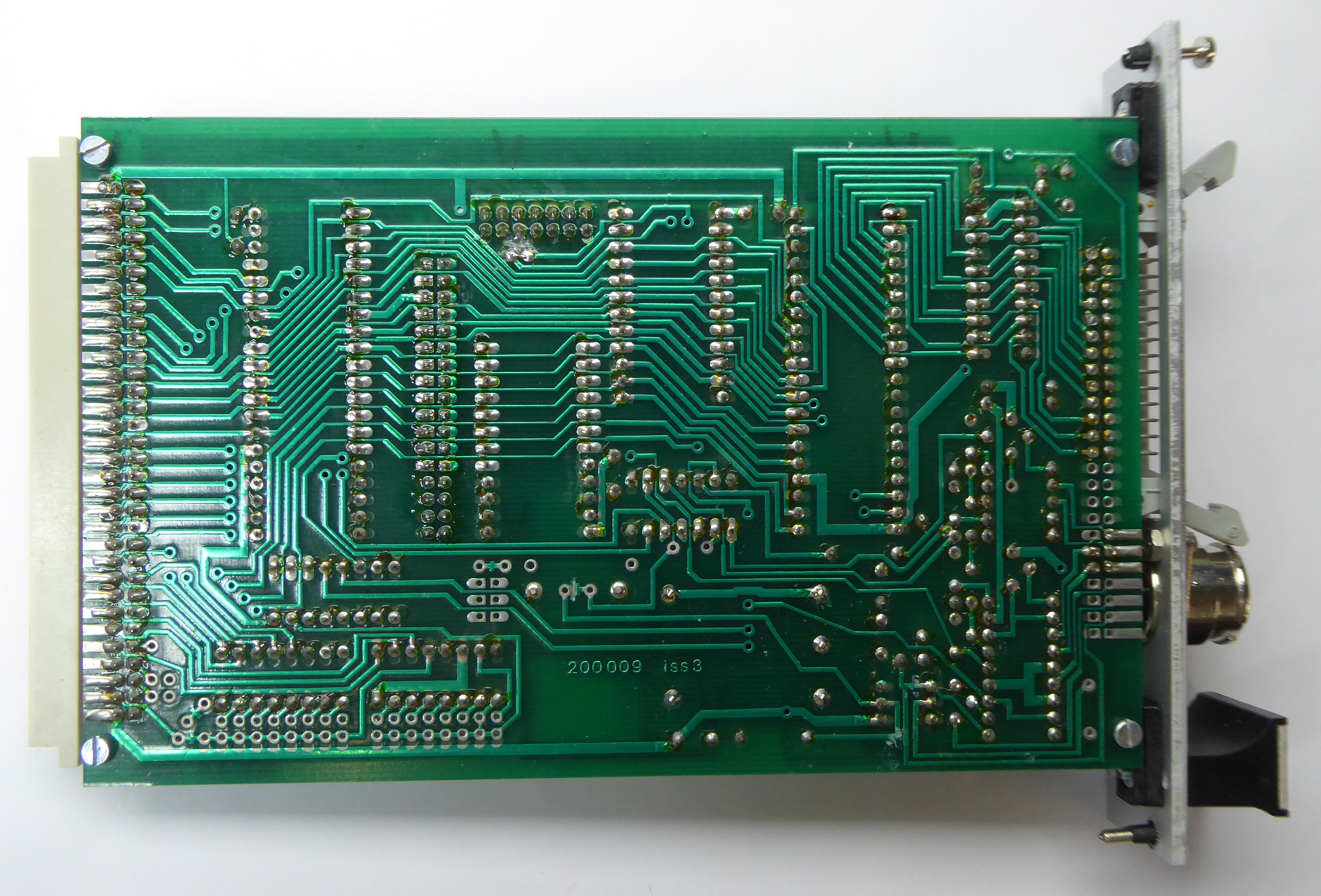
200.009 Issue 3 PCB [0]


200.009 Issue 2 PCB [3 System 4]


Replica Board: